They say that the part of a chain that will fail first is its weakest link. Now concerning the center latches that hold the Trailmanor closed, I believe that the part that is most prone to fail is not the latch itself because it is made out of steel and it’s connected to the trailer with steel bolts. Steel can take a lot of punishment before it fails. It would have to be under very extreme circumstances for that to happen. What I do believe to be the weakest part of the latching system is the front shell catch pin bracket and the way it’s held onto the trailer. As it turns out, it’s held on by just 4 sheet metal screws that are screwed into a square aluminum tube that runs the length of the underside edge of each shell. Now anyone that owns a trailer made with aluminum knows that aluminum is not the best material to screw into and expect it to hold with just sheet metal screws when stress is involved!
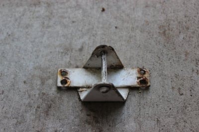
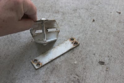
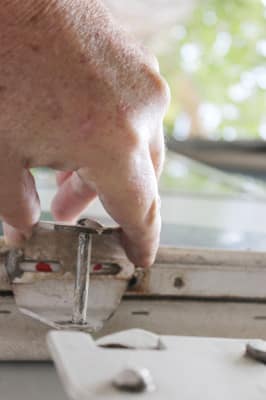
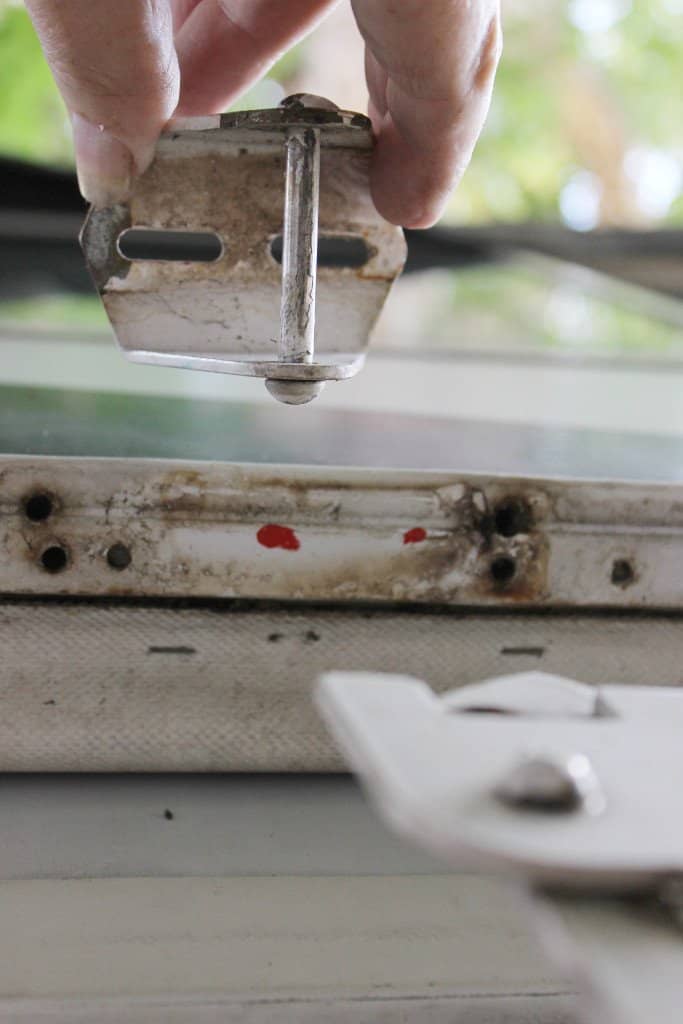
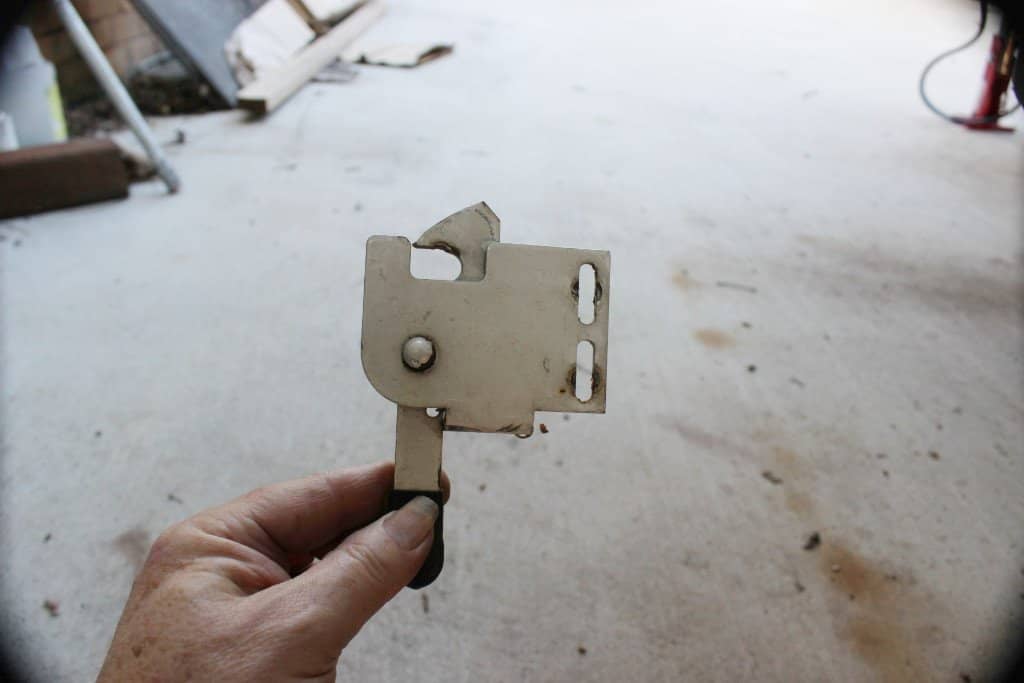
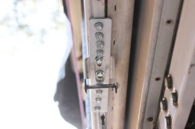
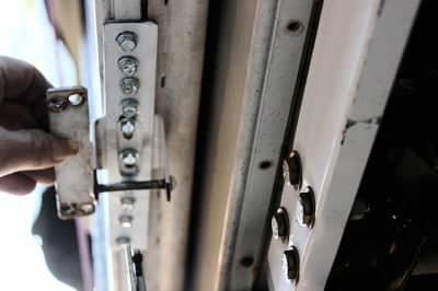
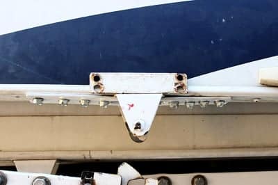
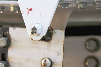
On May 23, 2016 I received an email from Ray Vanegas, a fellow 3124 TM owner who was having trouble with his roof leaking and also his center latch catches. It seems that the catch brackets were pulling out from the aluminum square tube that runs the length of the bottom edge of the trailer and stripping out the holes. OOOOO! Now that’s a problem that I don’t want to encounter ever. So I decided to do something about it. I had never given this any consideration until Ray dropped me an email after seeing my website about the roof. Well I called Ray and we discussed what I had done and how to do it and that was that on the roof (I hope you get that fixed Ray). But the catch pin brackets were another thing indeed. So I went out and took a look and sure enough there is a potential problem with the factory set up. I did not have a clue about this until I took one side catch pin bracket off (image 1892). The bracket has a plate that runs across the base of the bracket and that is screwed into the aluminum square tube on the bottom edge of the shell with 4 sheet metal screws. Now I thought since it is one piece (welded together) that it should be easy to just add a couple of screws to that plate. But it’s not welded like I thought but two different pieces (image 1893) and the base of the bracket has slots in it so you can adjust it back and forth. Now why didn’t they (the factory) put screws in those slots? Beats me!
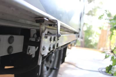
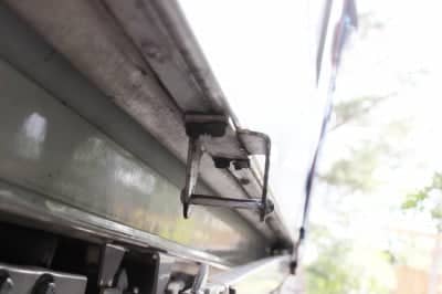
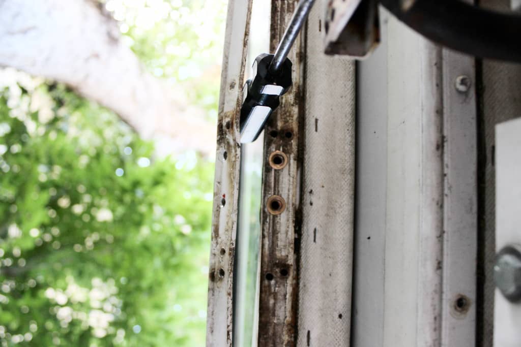
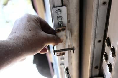
Now they did use these slots on the rear shell to hold the catch pin brackets to the aluminum edge tubing. But on the front they just used a plate to hold everything down and with only 4 screws! This isn’t as critical like the rear shell because the front shell also bears the burden of holding down the rear shell as well. So when things get to bouncing up and down, like on a dirt road, you can see how the rear shell would exert its force on the front shell, not to mention the front shell bouncing up and down as well. This is what happened to Ray and why his screws pulled themselves out of the holes in the aluminum tubing. I also noticed, that by the front catch pin bracket being just held down by that plate, that there was nothing to stop it from drifting to the left or right. This is what I noticed on my trailer, and, it can make it difficult to latch (images 1890, 1891). But worse than that, there is nothing to stop it from moving forward or backwards. Too far forwards and the latch hook will not engage the pin on the catch or it will catch, but just barely and then slip off while in transit…Too far back and the hook does not close properly. It has to be right in the middle to seat right.
Now they have these slots so you can adjust the catch pin brackets, but they only use them on the rear shell catch pin brackets (which are not so critical because the front shell hold everything together). With just that plate holding the front catch pin brackets in place, there is no provision for keeping it in place other than friction. Once set at the factory it’s good to go. But 10,000 miles of bad road and they move all over the place. Something had to be done. This is what I did…and this one’s for you Ray!
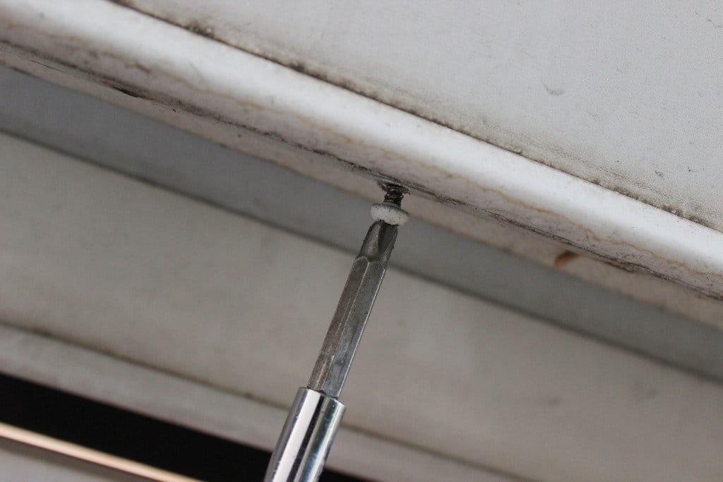
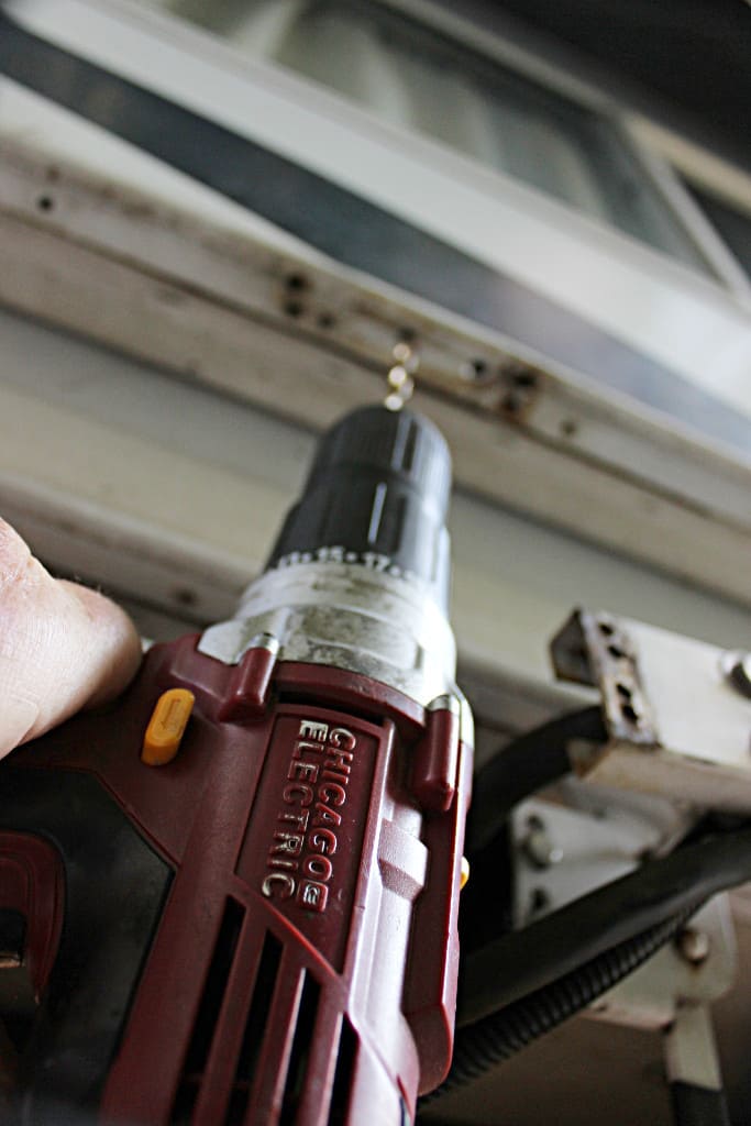
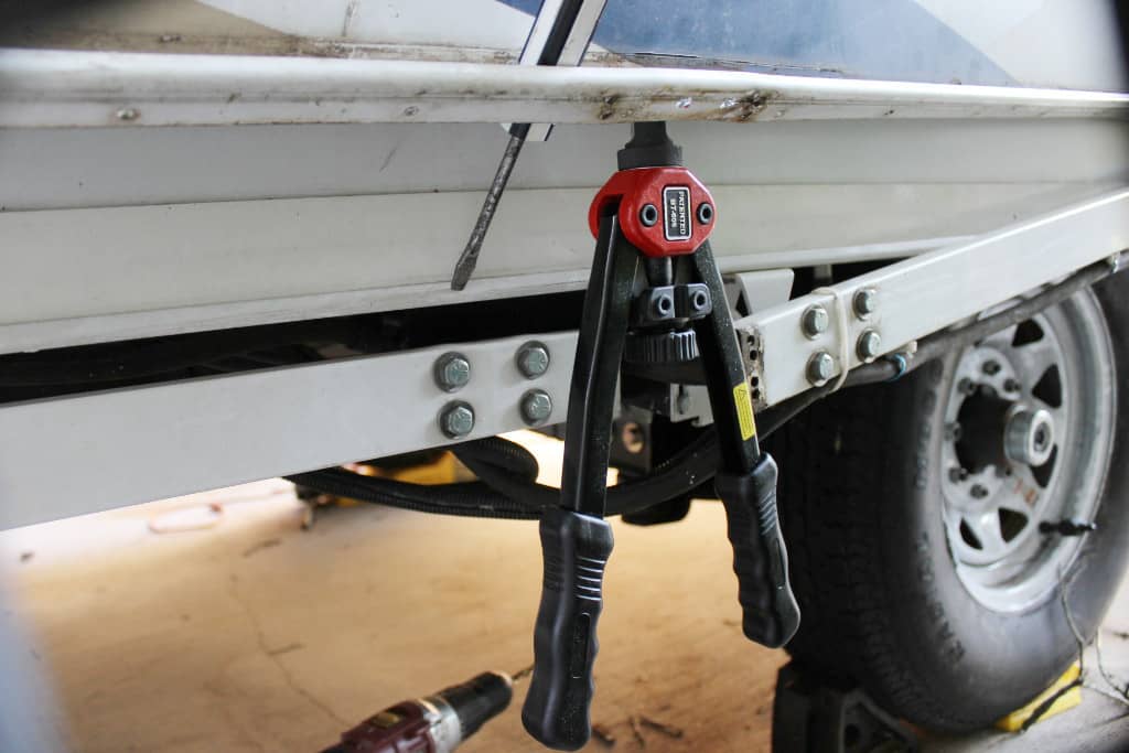
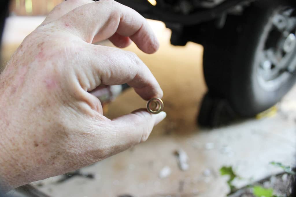
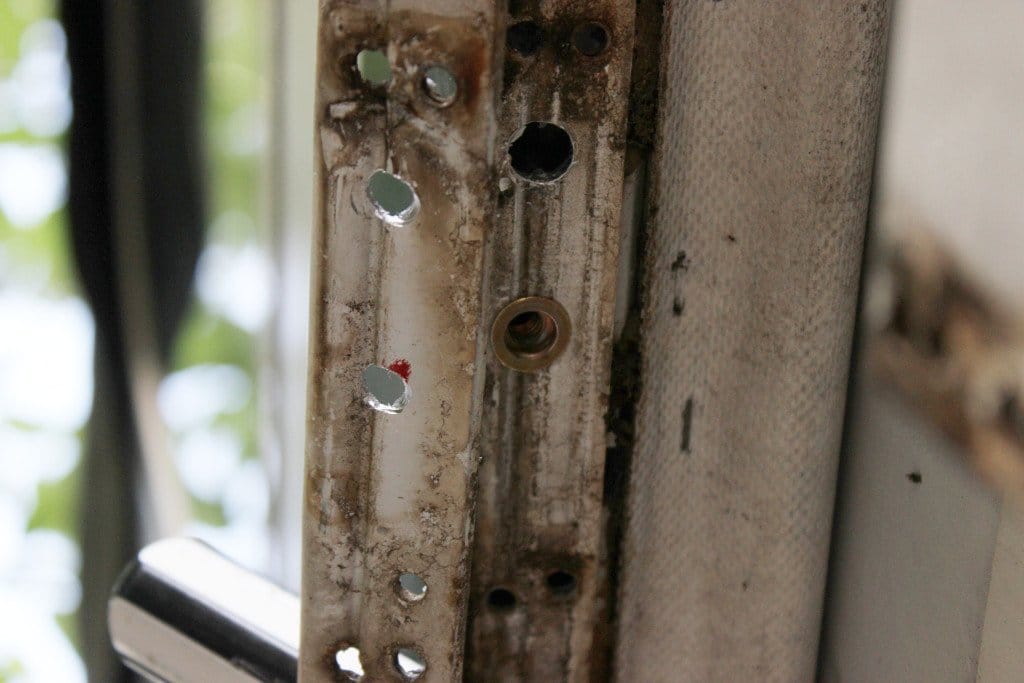
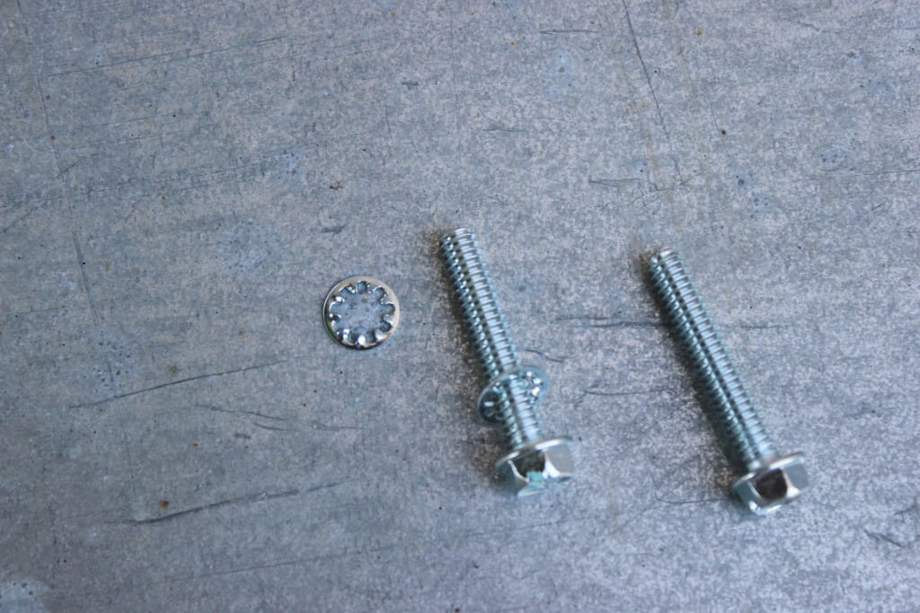
The first thing to do is to remove the old catch pin bracket that is held on by the 4 sheet metal screws (image 1893). Then center the slots of the catch pin bracket with the aluminum molding and line it up so as to be where it will lock onto the middle of the latch hook and mark two hole in the middle of the slots (images 1895, 1896). Remove the latching mechanism (image 1897) and drill two, ¼” pilot holes for the machine screws (image 1898) thru the molding and into and thru the aluminum tube as well. Next you need to loosen the molding by removing the screws that hold it up (from the front lift arm pivot point to the wheel well or door depending which side your on … image 1894). Now I used the riv-nut threaded inserts to hold the catch pin bracket in place (image 1901). That way if you need to adjust it, you can, and not have to worry about stripping out the aluminum holes with sheet metal screws. Plus riv-nuts are much stronger than sheet metal screws when it comes to holding something in place. The ¼” riv-nuts (meaning they take a ¼” machine screw) are 3/8” in diameter (image 1900) so you will want to use a drill bit 1/64” smaller than 3/8” when you drill out the holes for the riv-nuts. You want them to have a nice snug fit so they don’t turn when you set them into the holes with your riv-nut tool (image 1899). They work like pop rivets but leave a threaded insert to screw a machine screw into (image 1902). Set two riv- nut inserts (image 1903… you can see that on the driver’s side of the TM I didn’t take the molding all the way off and used a screwdriver to pry it back so as to have the room to work to set the riv-nuts). Next, put the molding back on and screw it down. I wanted the riv-nuts under the molding so that’s why I did it this way. You can now install the catch pin bracket and for that I used two ¼” machine screws with internal spline lock washers (image 1904) to keep them from coming loose. Don’t tighten it all the way down, but leave enough room so you can slide the catch pin bracket back and forth for adjustment.
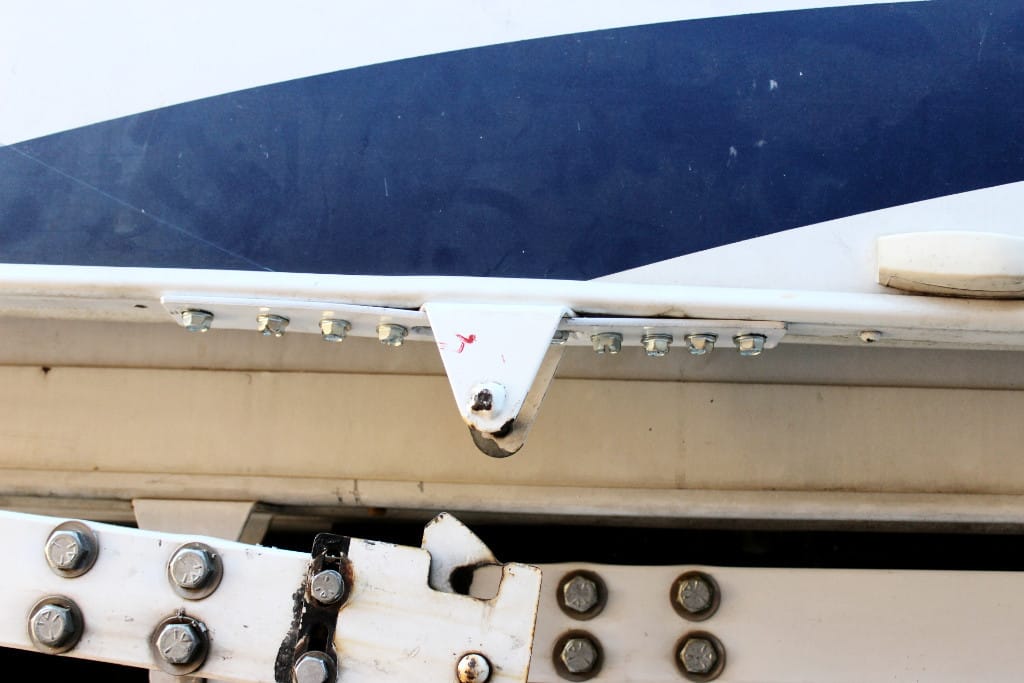
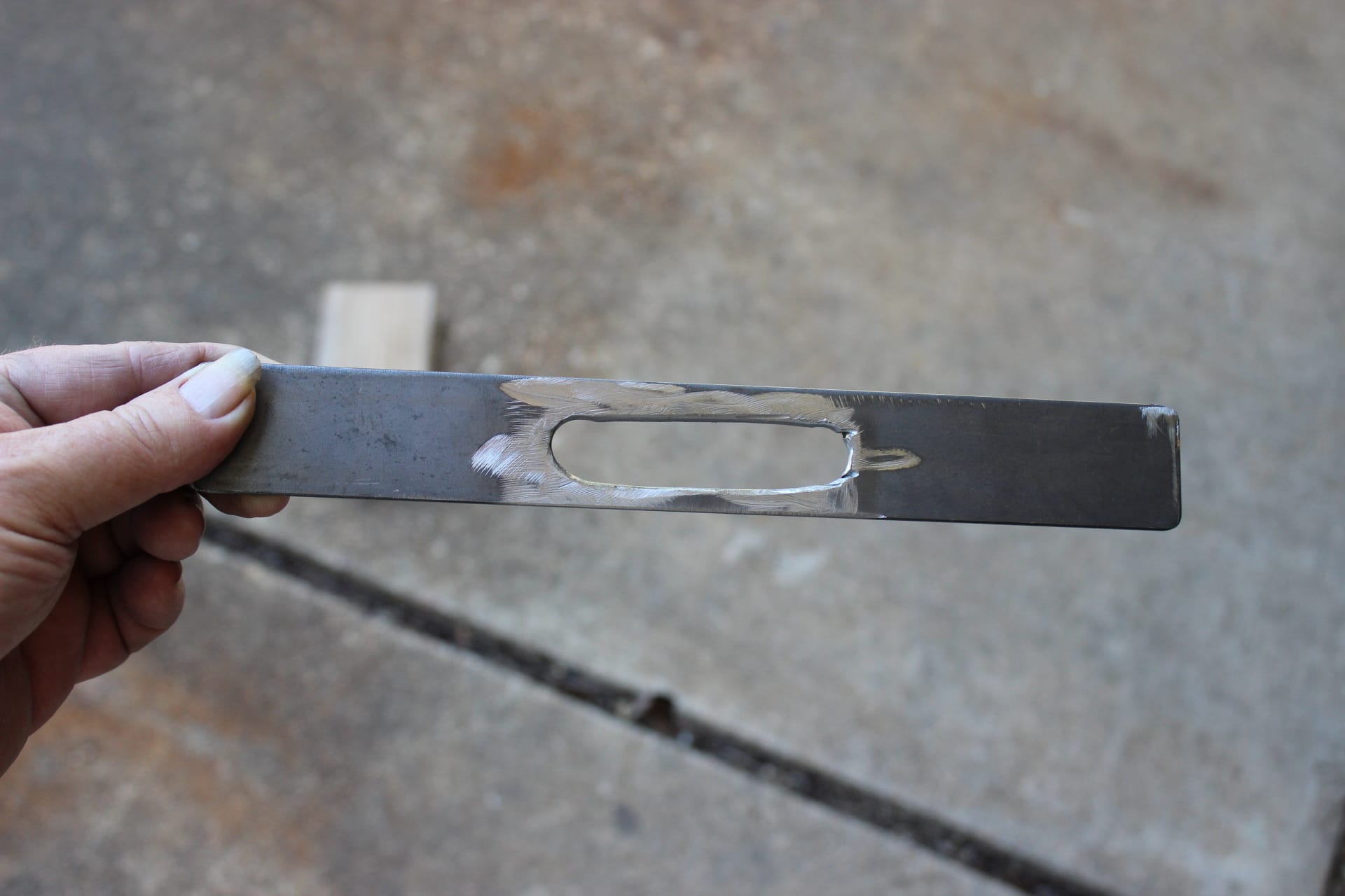
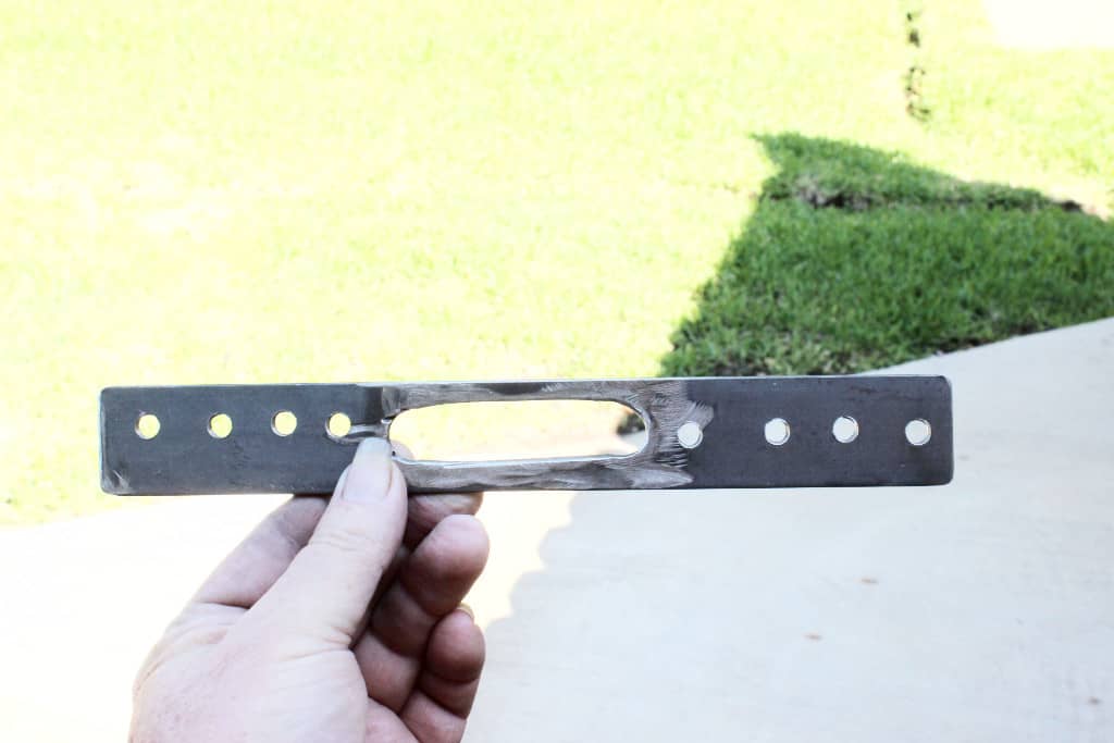
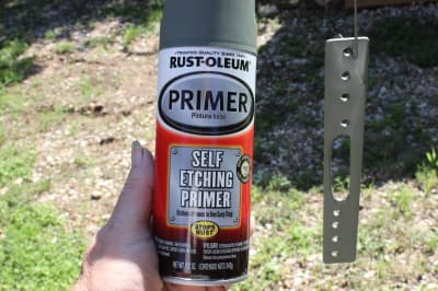
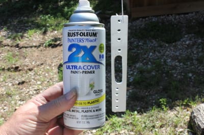
I was going to try to use the original plates that hold down the catch pin brackets, but it wouldn’t work, so I made new ones that are better. I took a piece of 1 ¼” wide steel plate that was 9 ½” long and drilled two ½” holes, 1 1/8” from the center (one on each end) so I could cut a slot with an electric cutoff tool for the screw heads of the catch pin bracket to stick thru. That way I could see the adjustment of the bracket (image 1912). Then I drilled four holes that were slightly bigger than ¼” on either side of the slot with four on one side right down the middle and the other four just a bit closer to the edge. This way they would clear the lift arm when it came time to put in the screws (image 1913). After cleaning the steel with paint thinner, I primed (image 1914) and then painted it white when the primer was dry (image 1915). Once the white paint was dry, I installed the plates over the catch pin base (images 1906, 1907) using ¼” x 2” sheet metal screws and the internal spline lock washers (image 1905). I drilled out the holes first with a bit a little smaller than the ¼” screws so the threads would grip nicely and screwed them in (images 1906, 1907). Before I tightened them all the way down I adjusted the catch pin base so as to strike in the middle of the latch hook (image 1911). Now my hooks aren’t going to undo themselves by living on the edge like they were before. I tightened machine screws on the catch pin brackets down first before I tightened the plates all the way down. You can really see the difference between the wimpy factory plates and the new ones I fabricated (images 1908, 1909, 1910). With 8 screws holding each plate down and with two machine screws holding each catch pin bracket in place, (that’s 10 screws on each side) I now have catches that aren’t going anywhere…well unless I take them there! Hey catches…. how about we go to Disneyland!