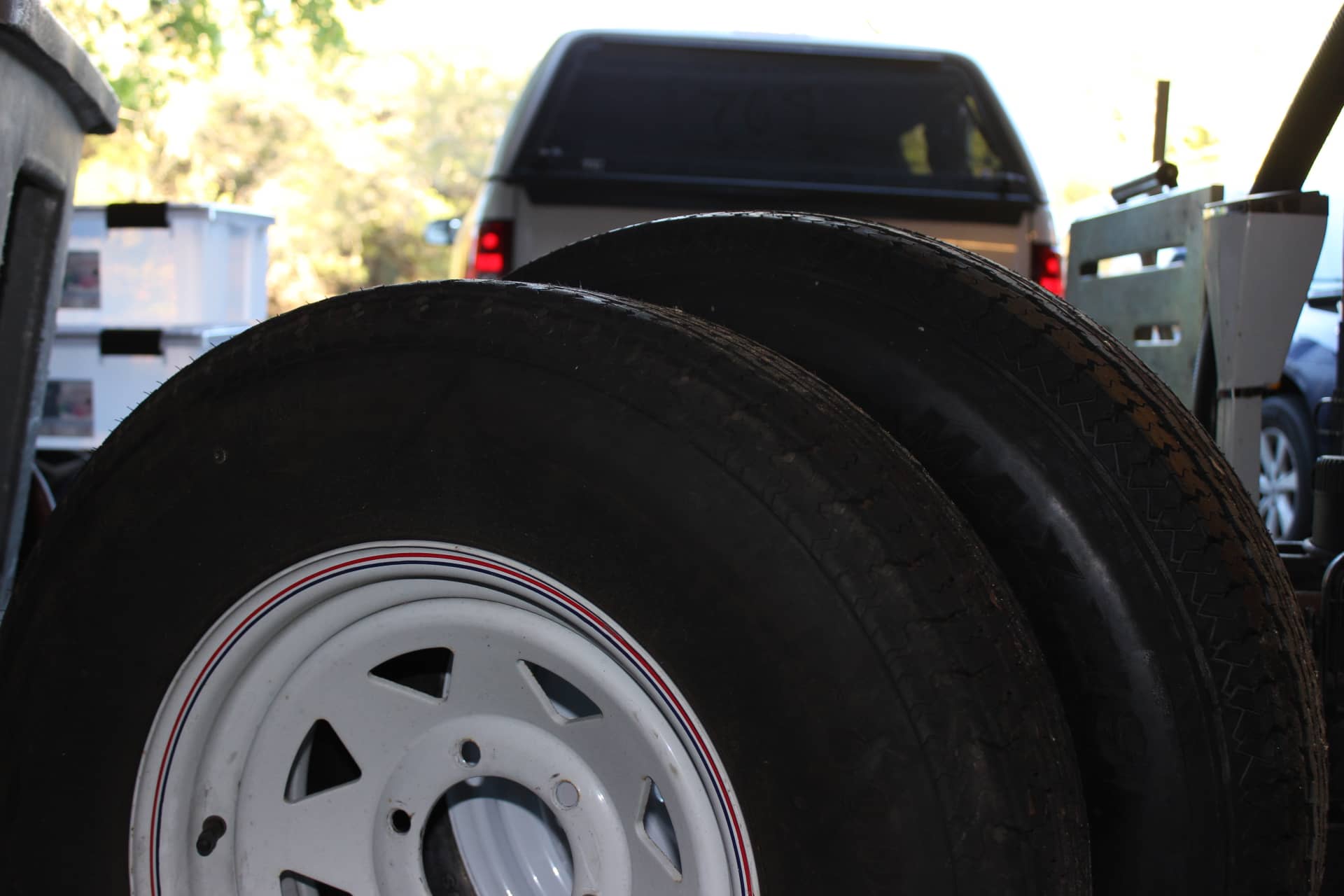
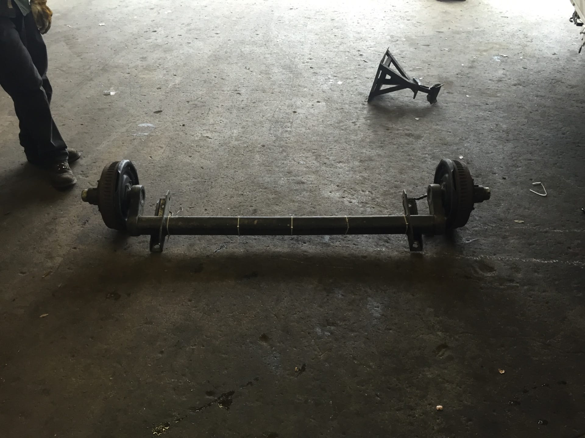
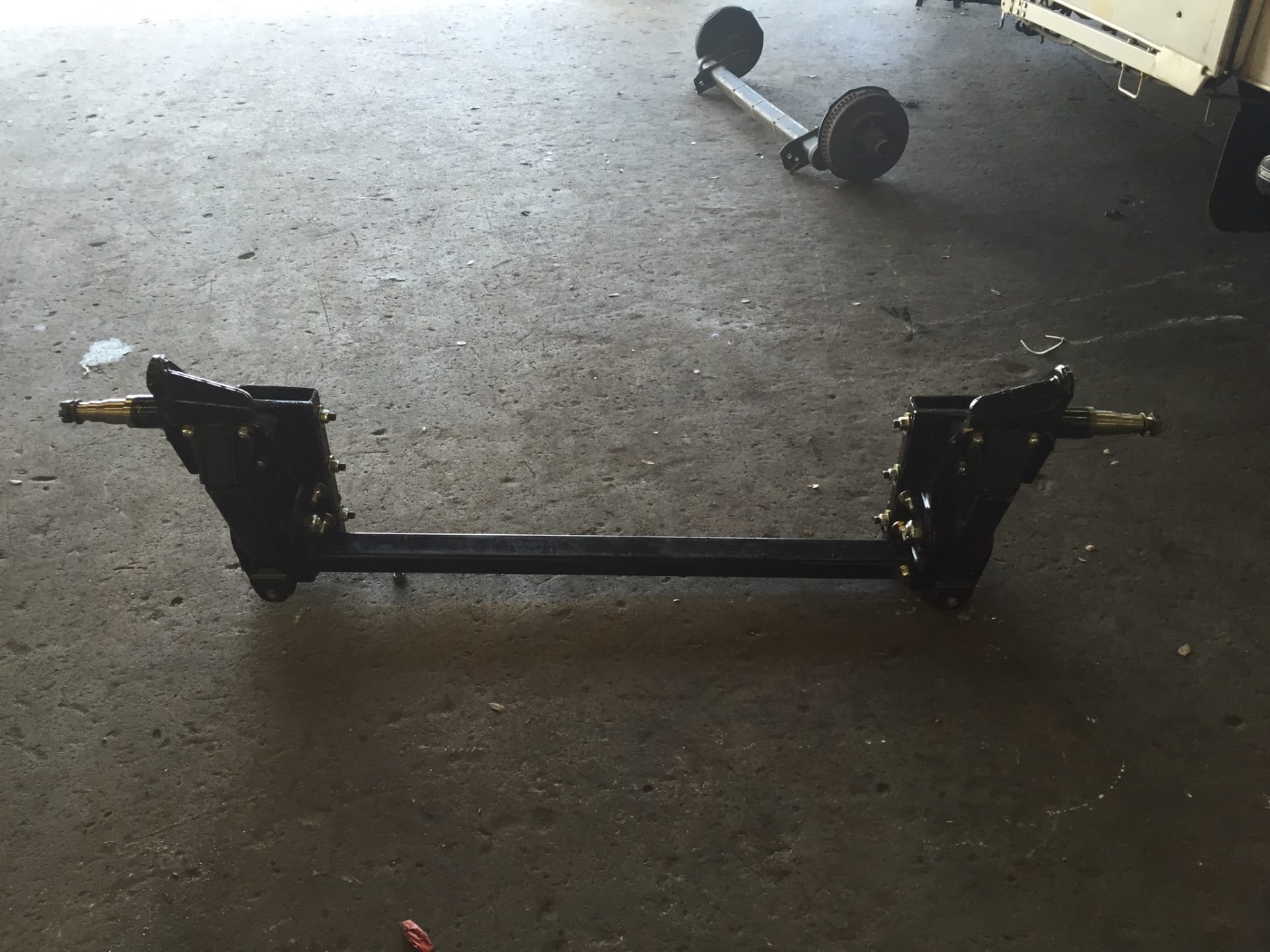
When I got back from our last trip to Californication I decided to go ahead with swapping out my Dexter Torflex 4400lb capacity axle with the new Timbren axle-less axles rated at 7000 lbs. (or 3500 lbs a piece) and the 15” wheels and tires to 16” wheels and tires. I had such good luck with my Maxxis tires that I bought 16” Maxxis tires for baby’s new shoes.
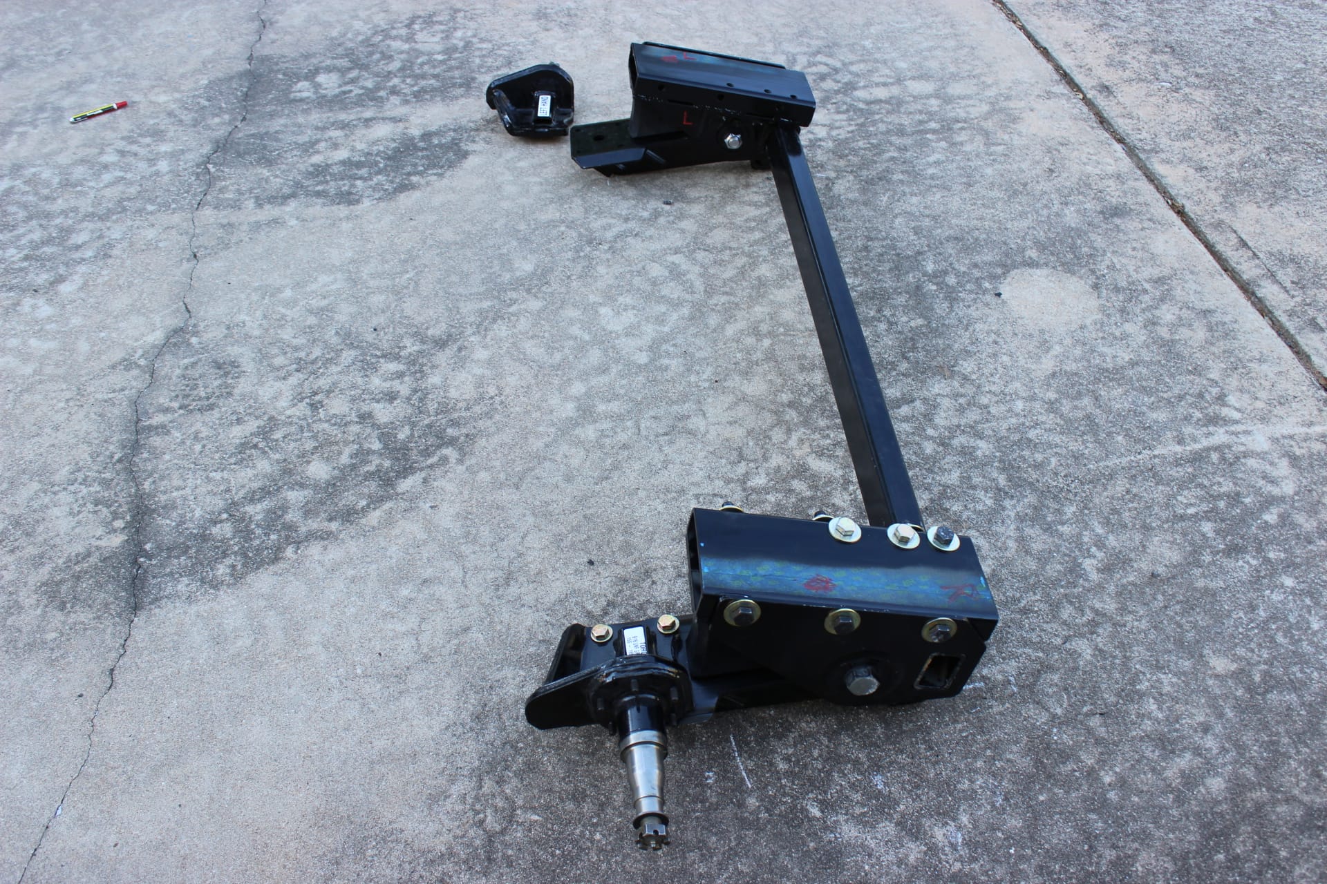
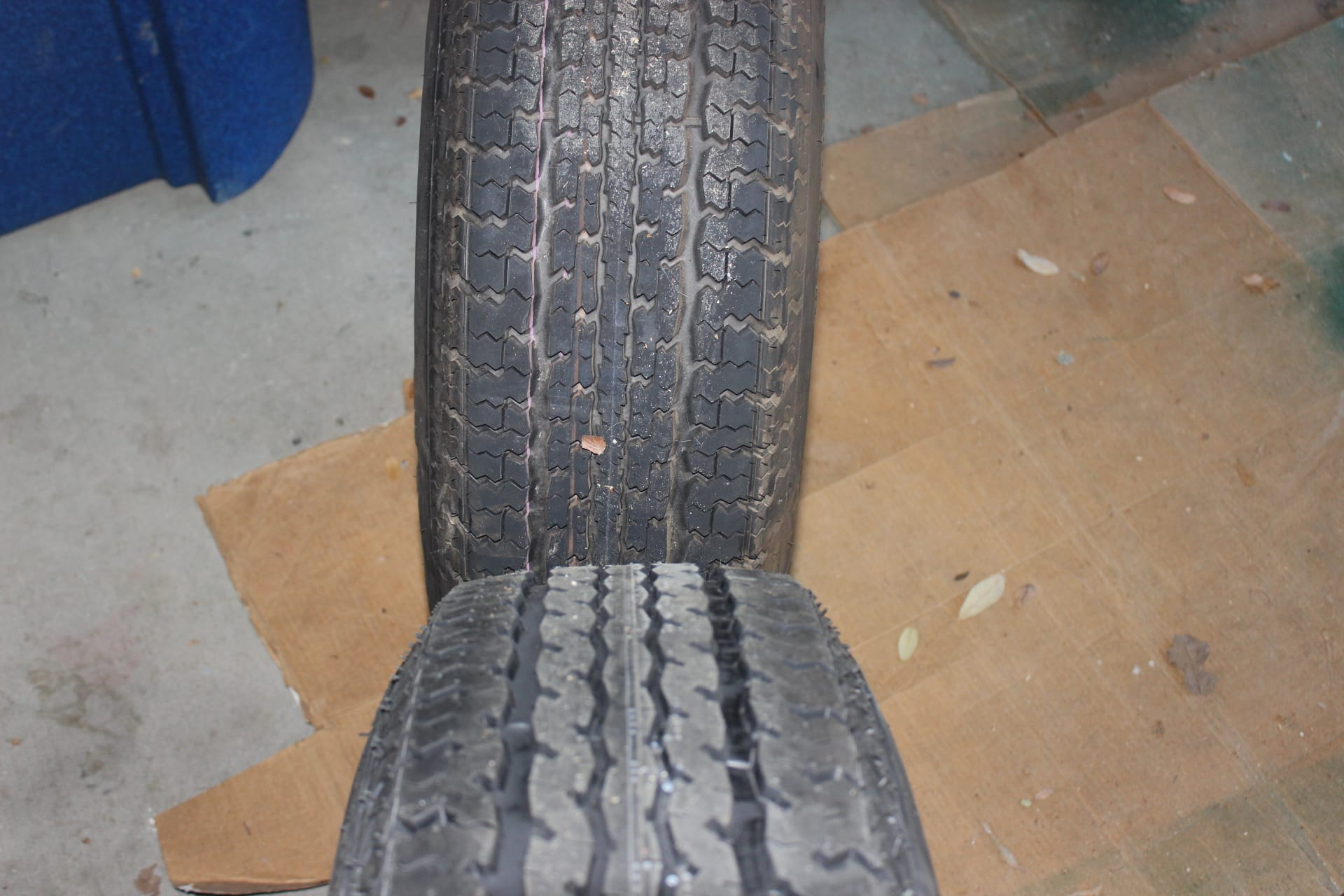
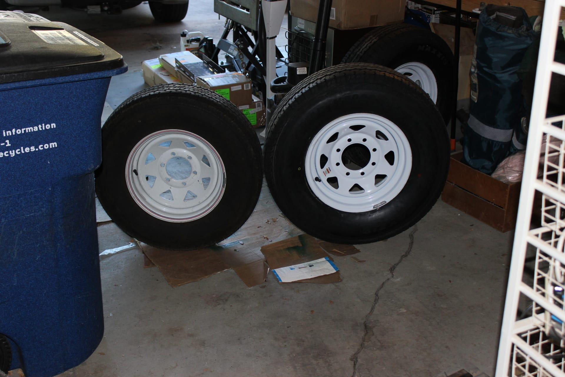
When they arrived I was impressed right away with the difference between the two. I instantly had them mounted and balanced. You can really see the difference when you can compare the two (images 1703, 1704, 1705). When I went to the 16” wheels they were 8 lug instead of the 6 lug wheels I had had with the 15” wheels (image 1706). All in all a much stouter system with higher weight capacity. This means that no matter how much stuff we load in the TM, we won’t be in danger of overloading the wheels or tires, and, with the 7K axles (image 1687), those as well. I’m all in favor of no worries!
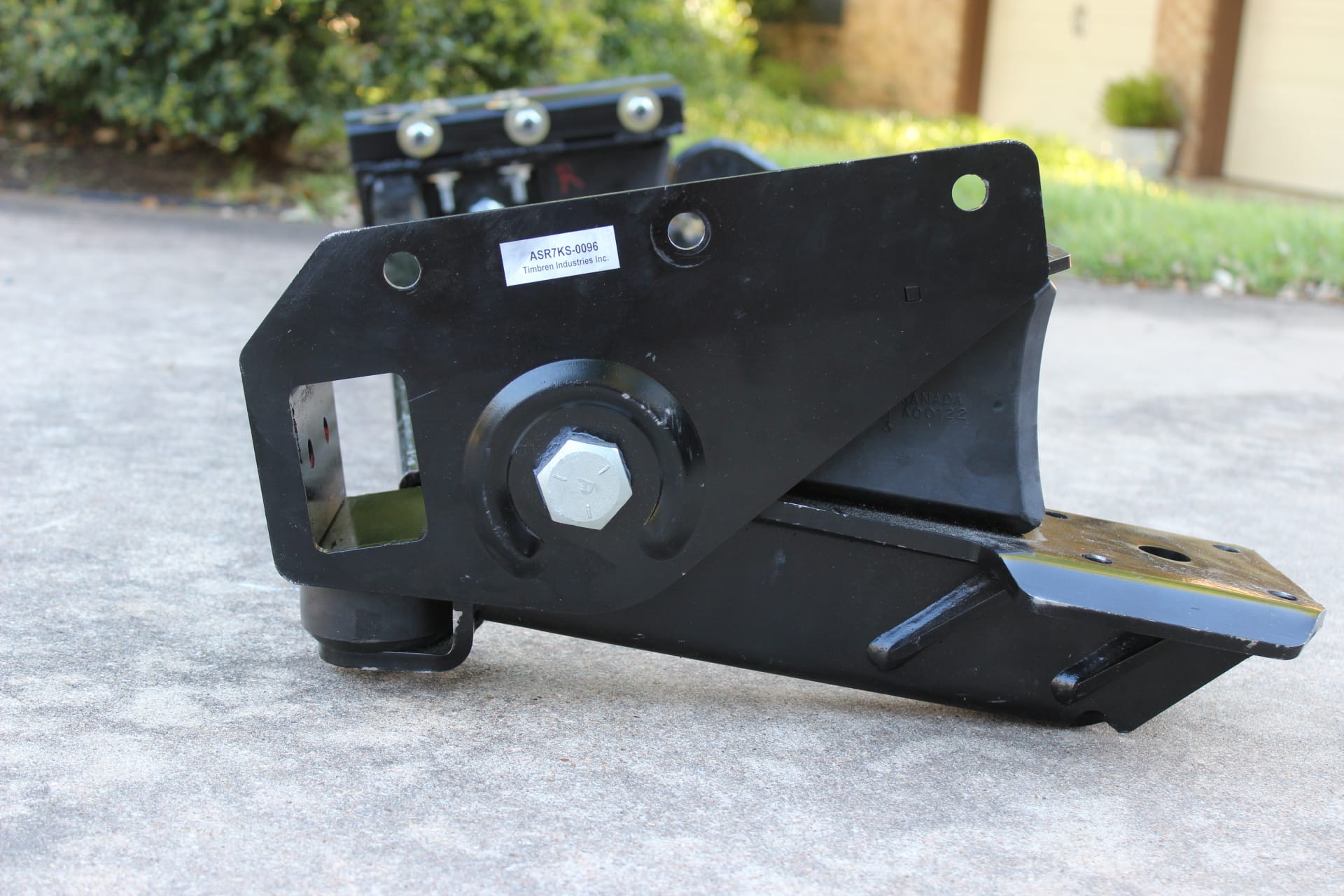
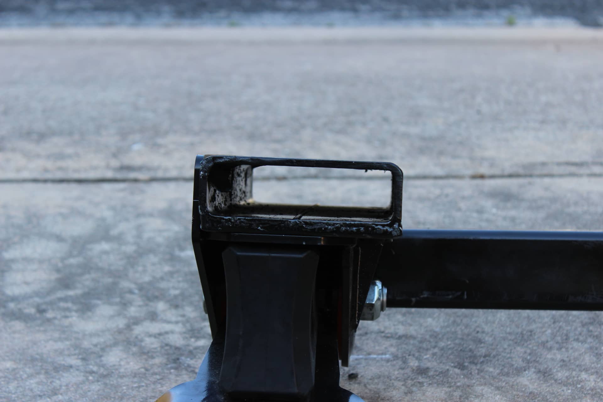
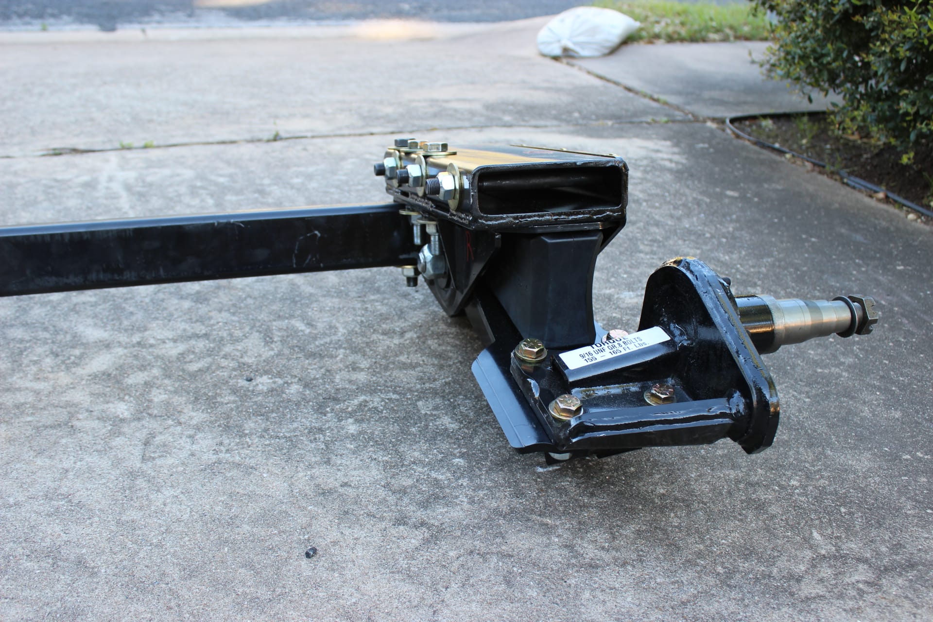
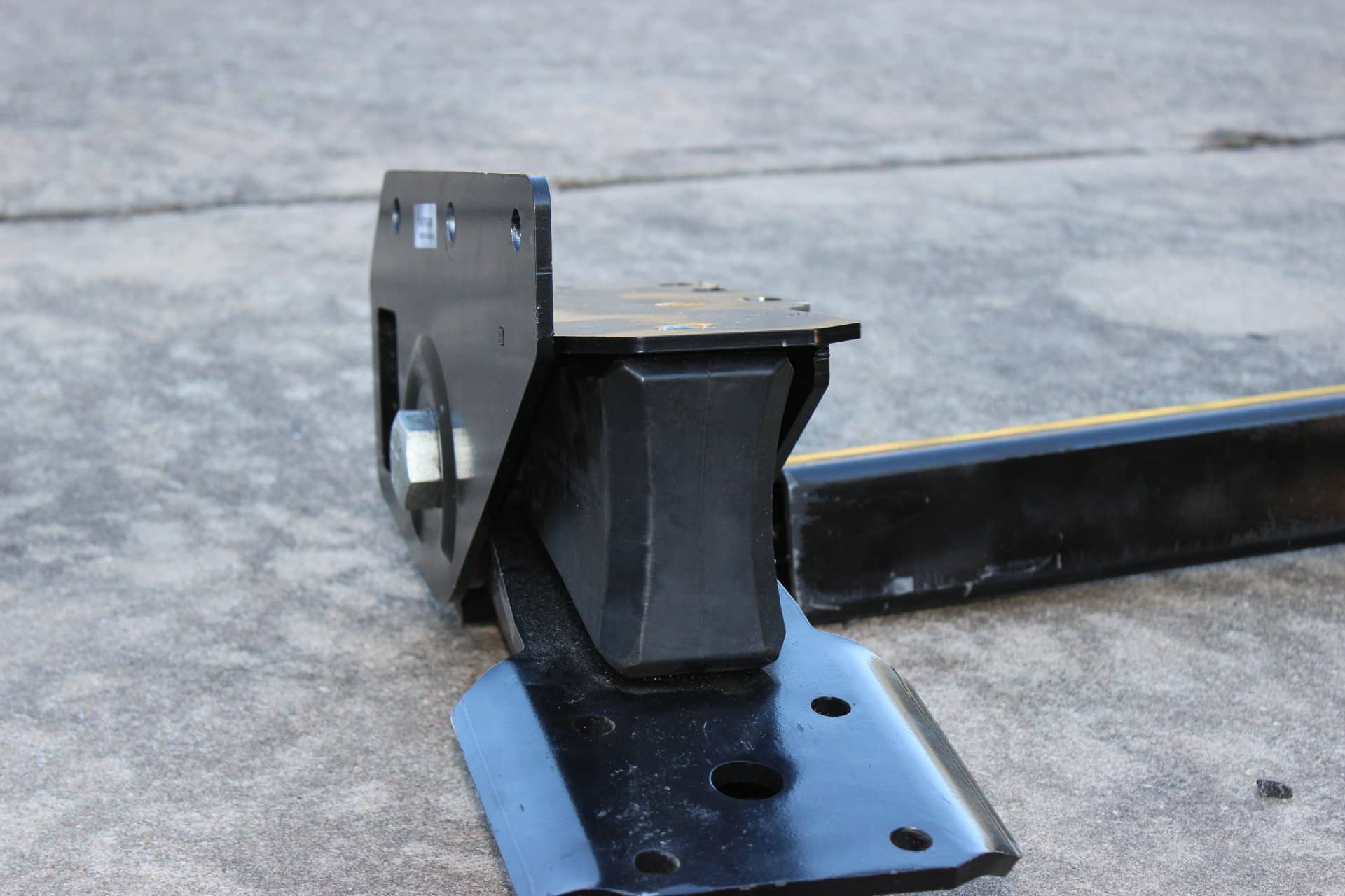
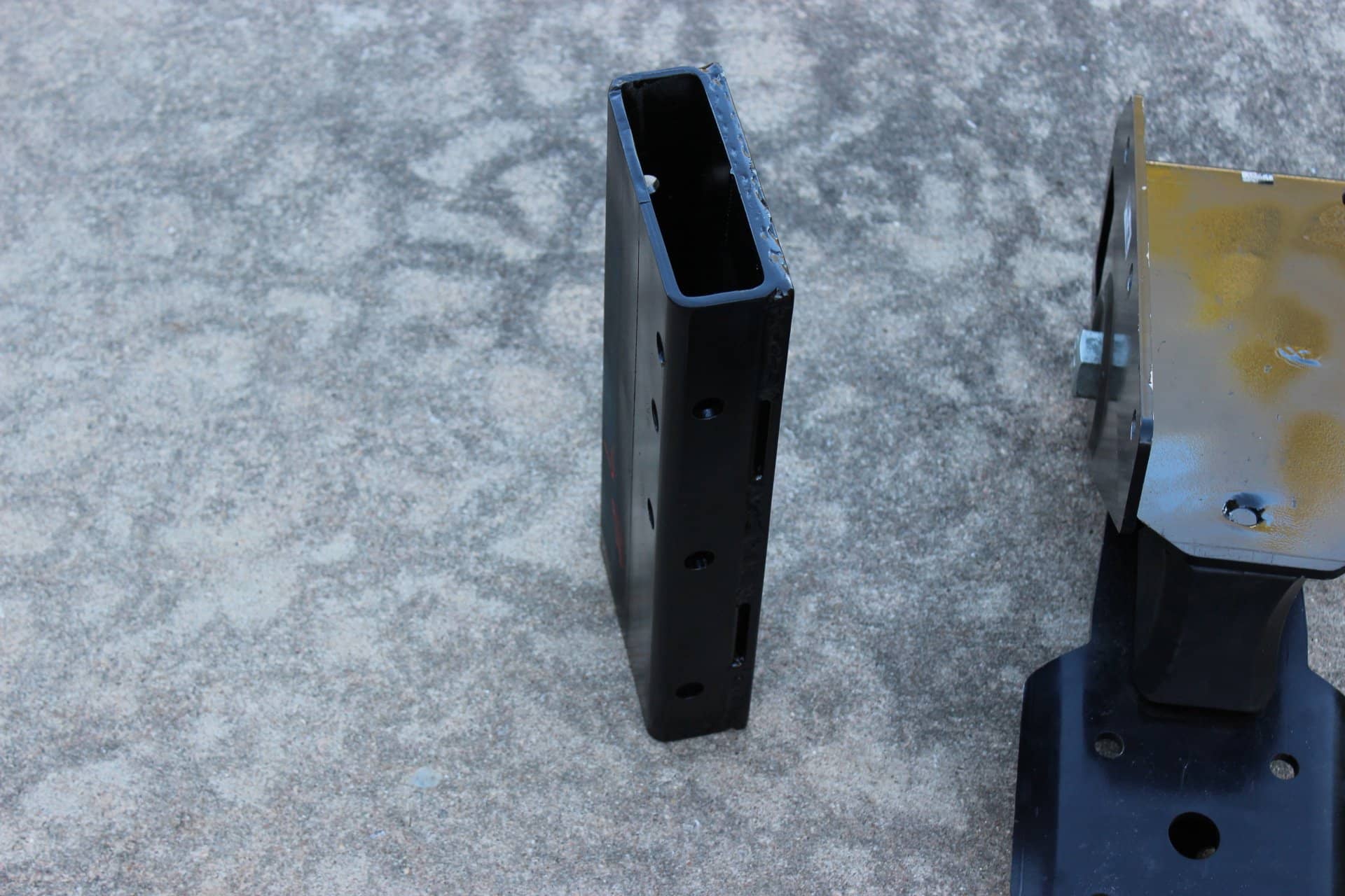
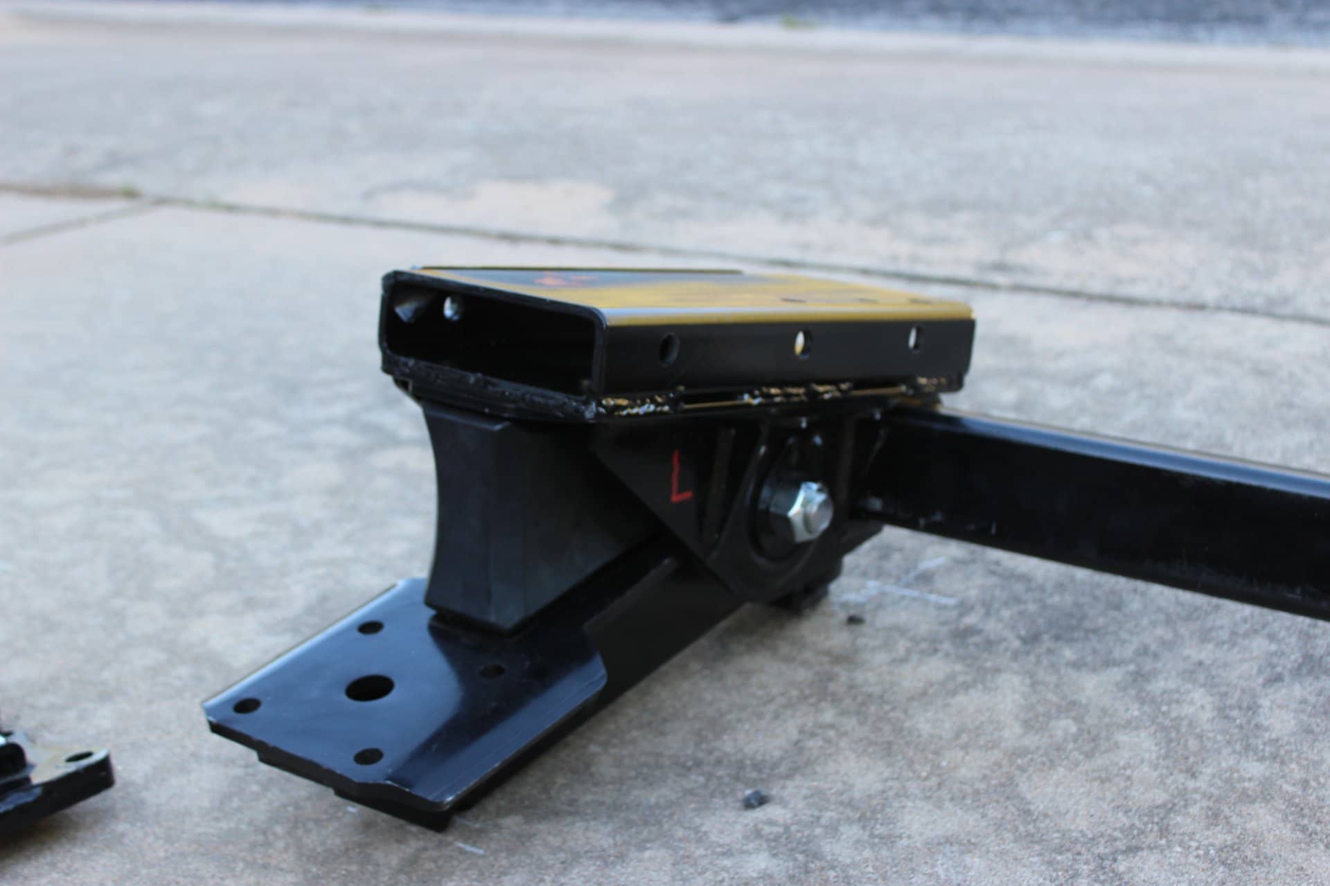
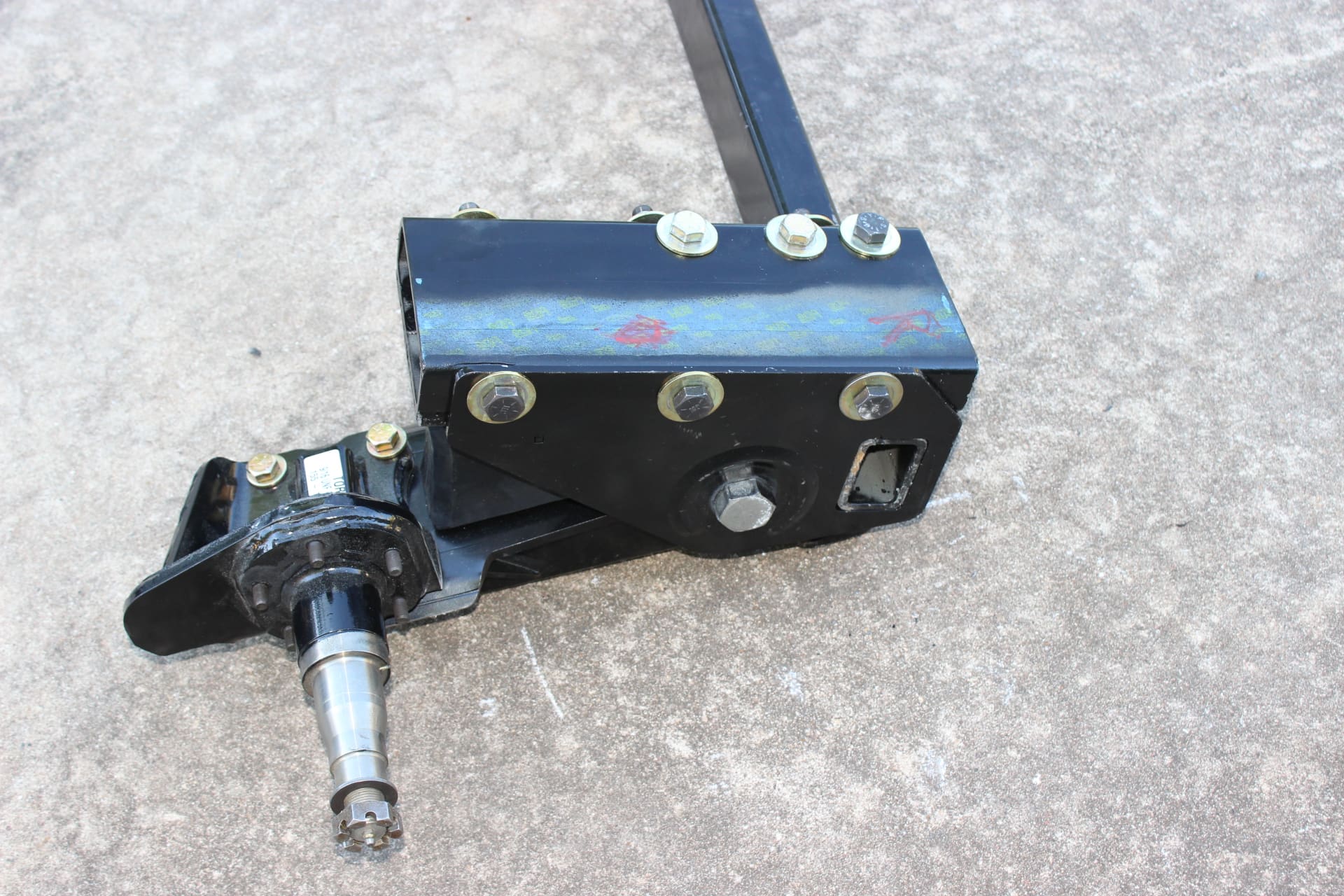
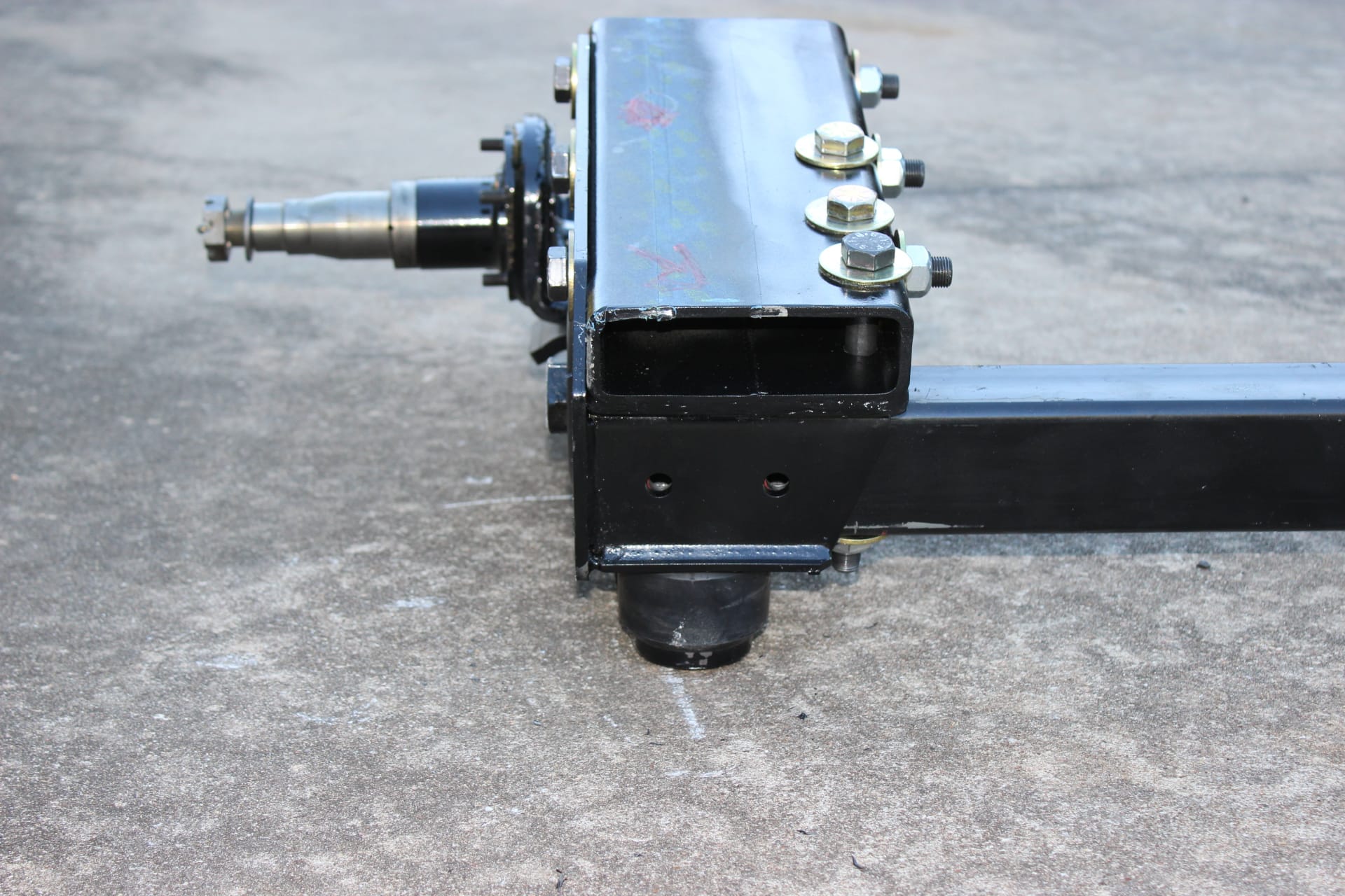
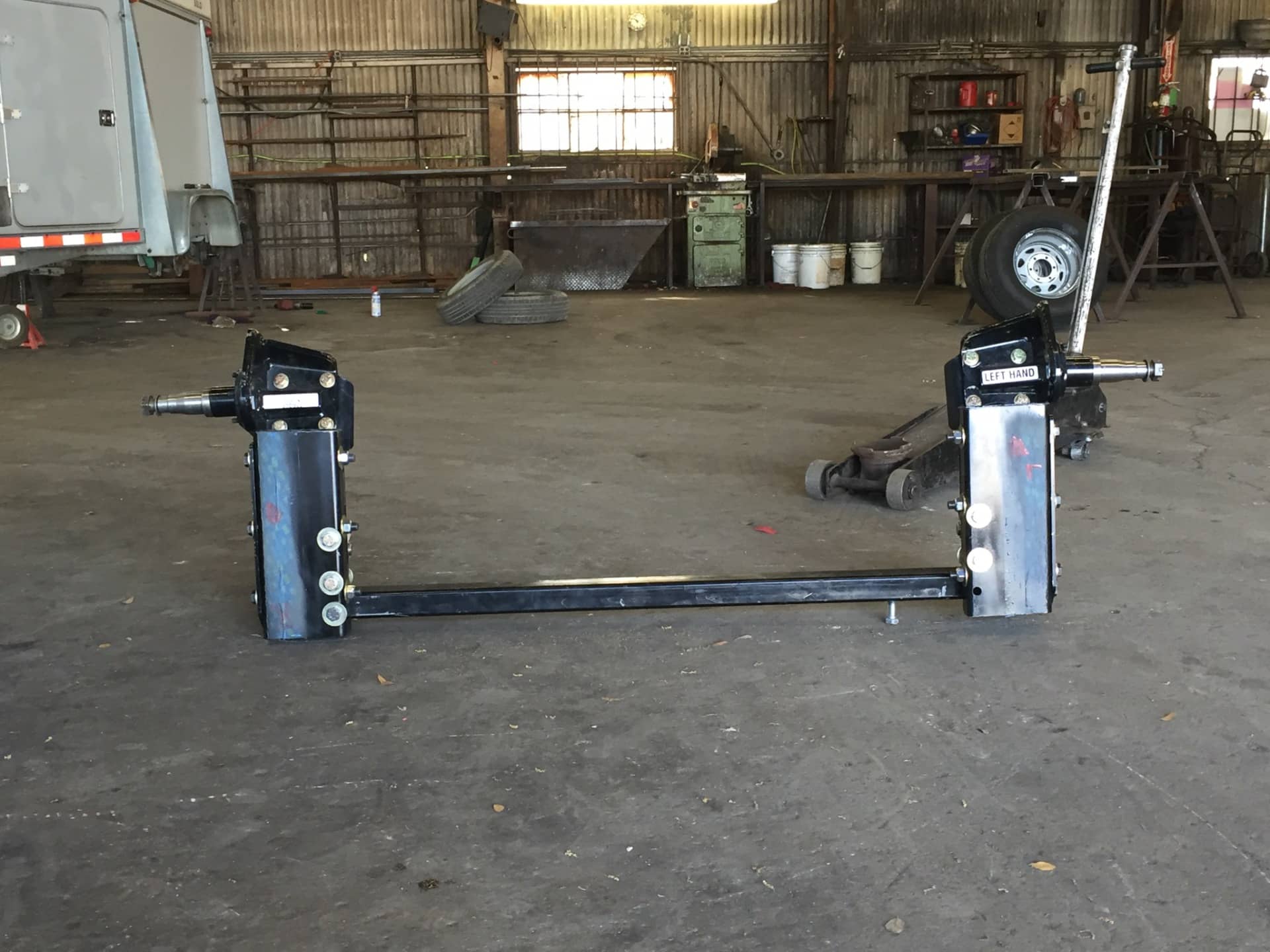
Going to the 16” tires meant that I would need some extra clearance between the tire and the wheel well. So what I did was to get a piece of 3/8” walled rectangular 2” X 6” tube that ran the length of the Timbren strike plate (the one that would butt up to the frame) to use as a spacer between the Timbren and the frame to raise it up enough. But that was not enough, because of the bolt placement would have been too high and would not have cleared the upper tube wall when the holes for the bolts were drilled. What I did was add another piece of ¼” plate the same size and had it welded to the 2” X6” tube (images 1693, 1694, 1695). Now it was perfect and the correct height and the bolts would now fit as they should (images 1696, 1697, 1698, 1700), three on the sides and three on the top of which one would help secure the cross member between the two Timbren (image 1699).
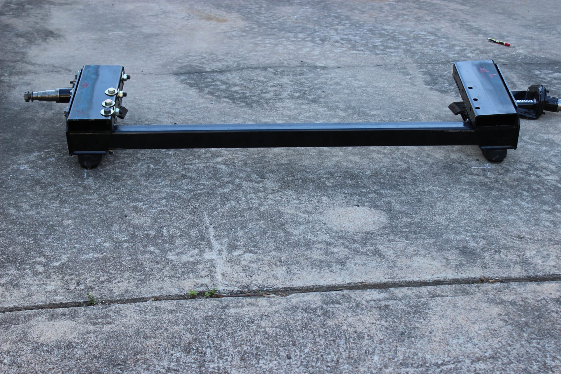
Timbren does recommend this cross brace and I also thought it a great idea (image 1701). There are also two holes on the end to secure the cross brace even better (images 1710, 1711).
This was way beyond my expertise and I wanted it done right so I took it to a local hitch shop (Spillars) in Austin Texas to have these installed (image 1712).
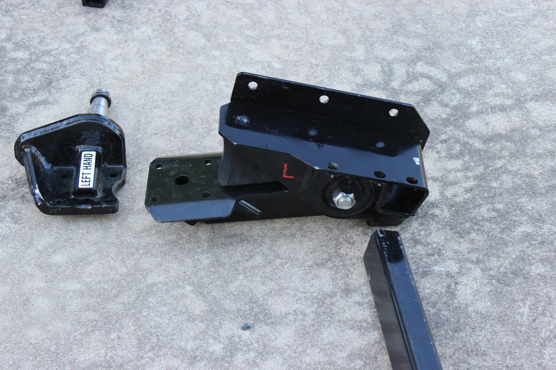
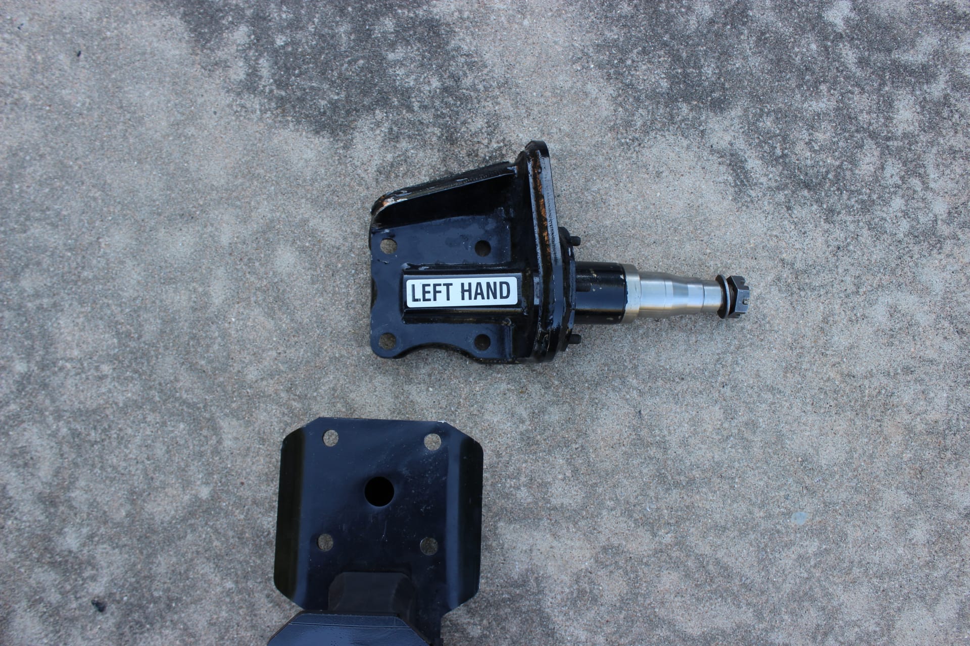
I took them the Timbrens (suspension and spindles… images 1688, 1689, 1690, 1691, 1692, 1696, 1697, 1698, 1699), cross beam (a steel 3/8” thick 2” X 3” rectangular tube images 1701, 1702), the riser plates (which I had drilled… images 1693, 1694, 1695), the hubs with bearings, 8,000lb capacity nuts and bolts and the mounted wheels and tires. I was told that the bolts that came with the Timbrens for mounting the spindles to the suspension units were not quite long enough to engage the lock nuts so eight (4 for each spindle), 1/2″ longer bolts should be bought to complete the assymbly. Why they give you bolts that are too short is beyond me. Just get some a bit longer and all will be right, but make sure they are 8,000lb capacity ones. They used my existing brakes (that I had bought last fall from etrailer ….image 1713 ) and put it all together.
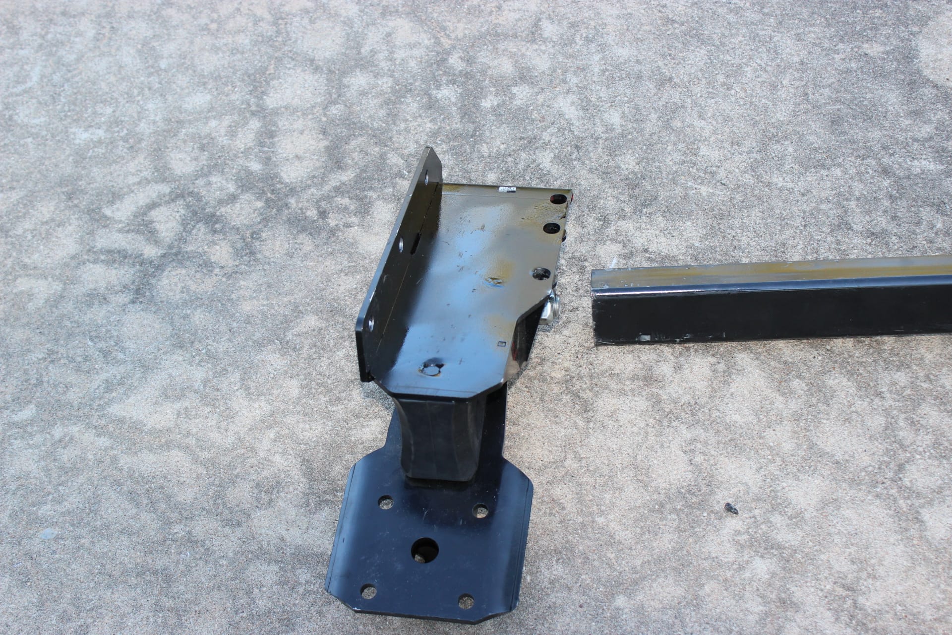
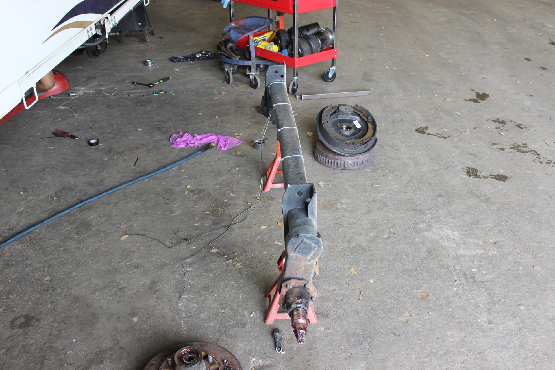
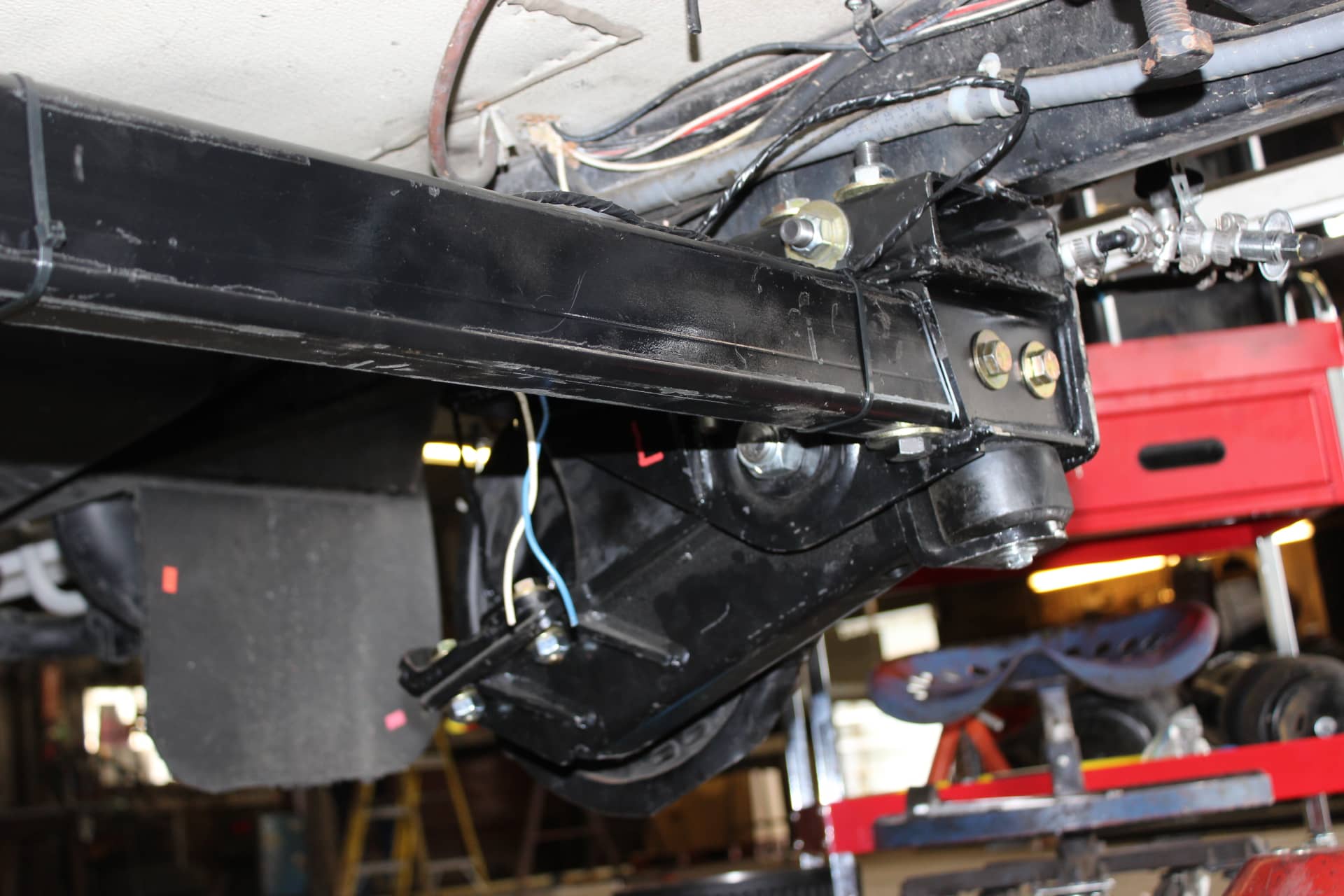
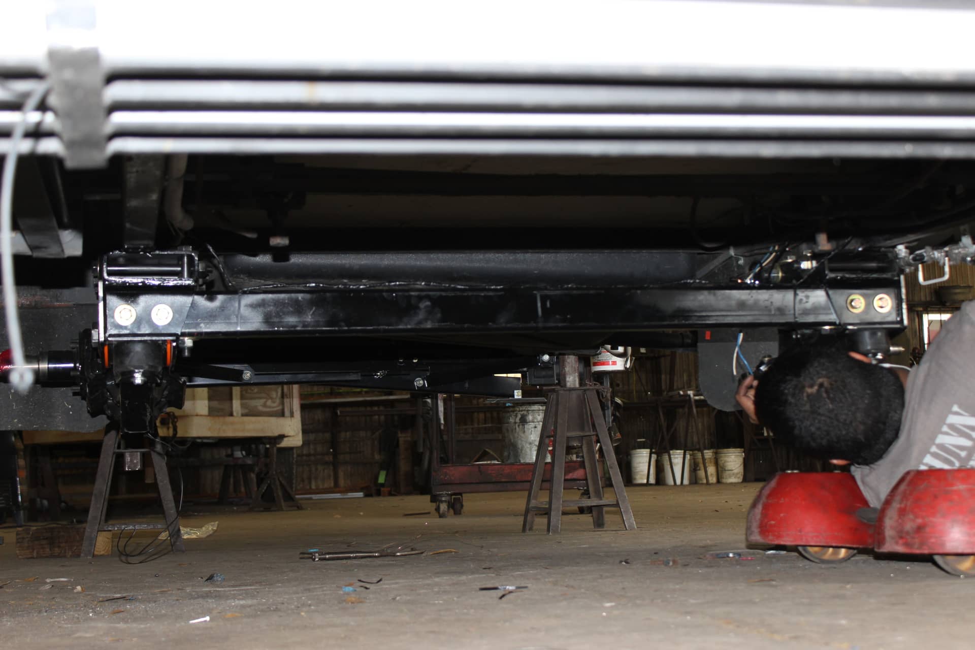
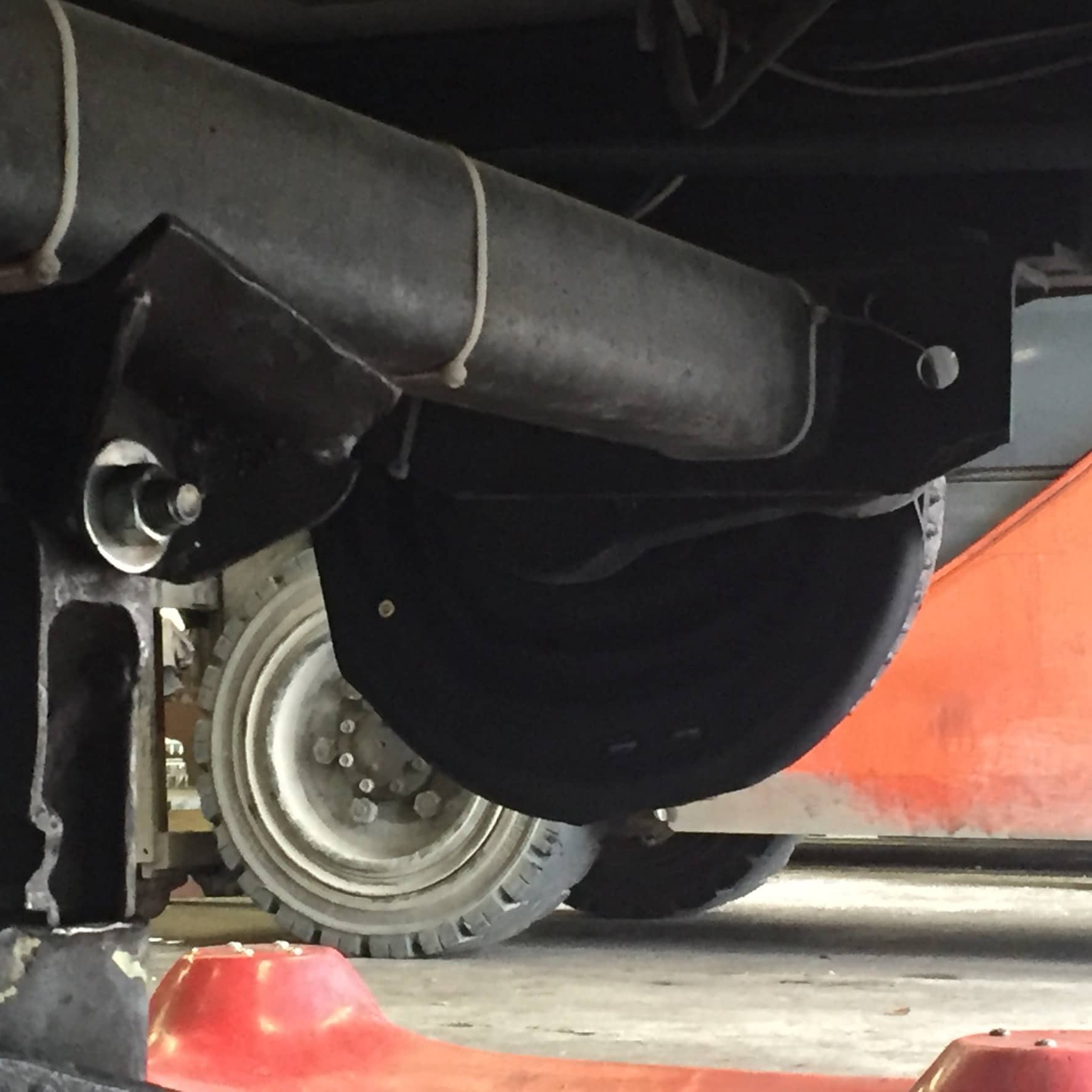
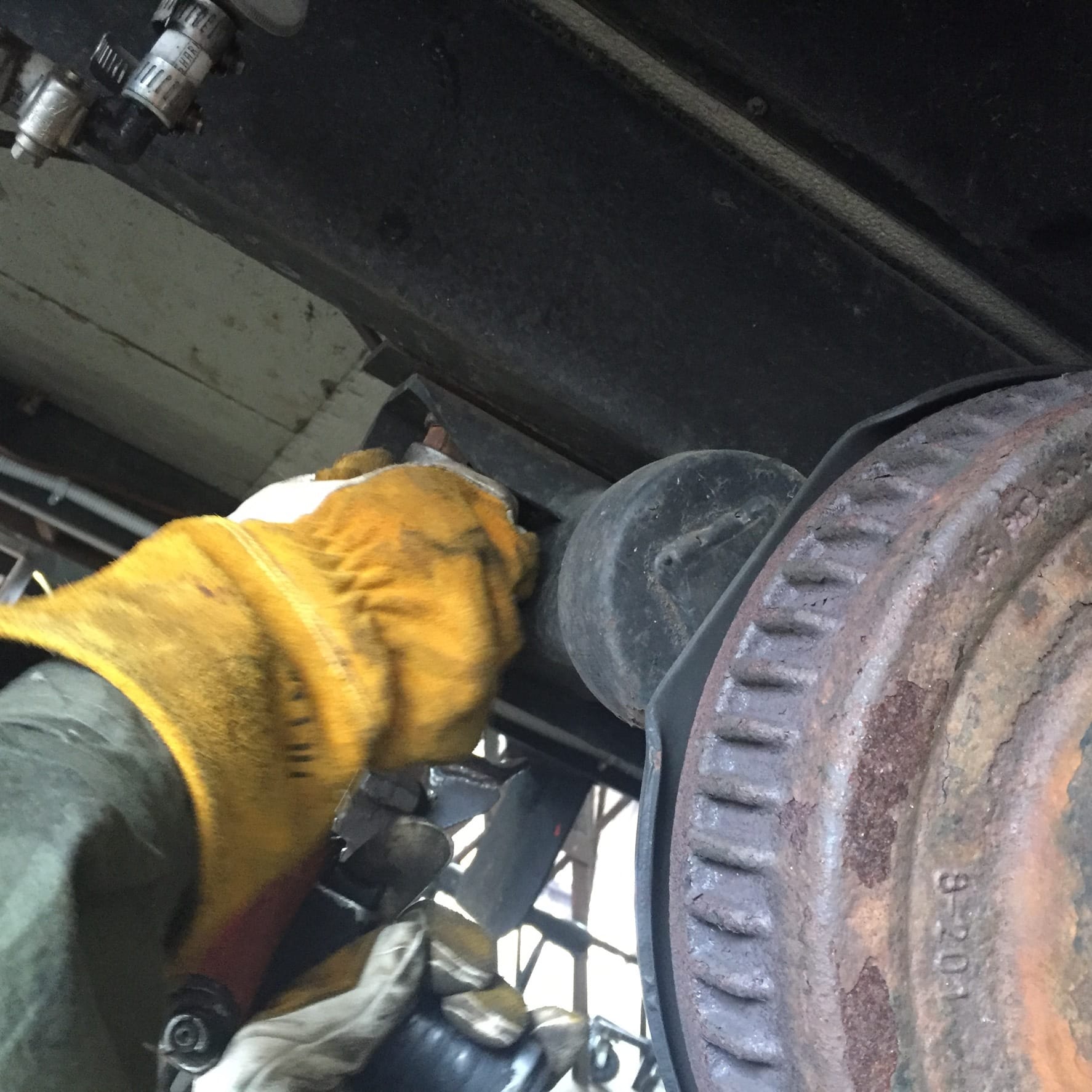
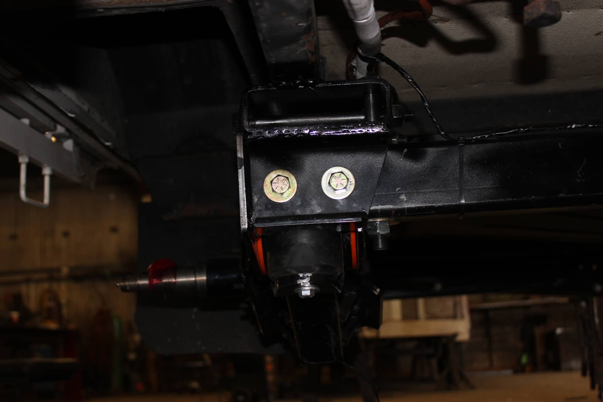
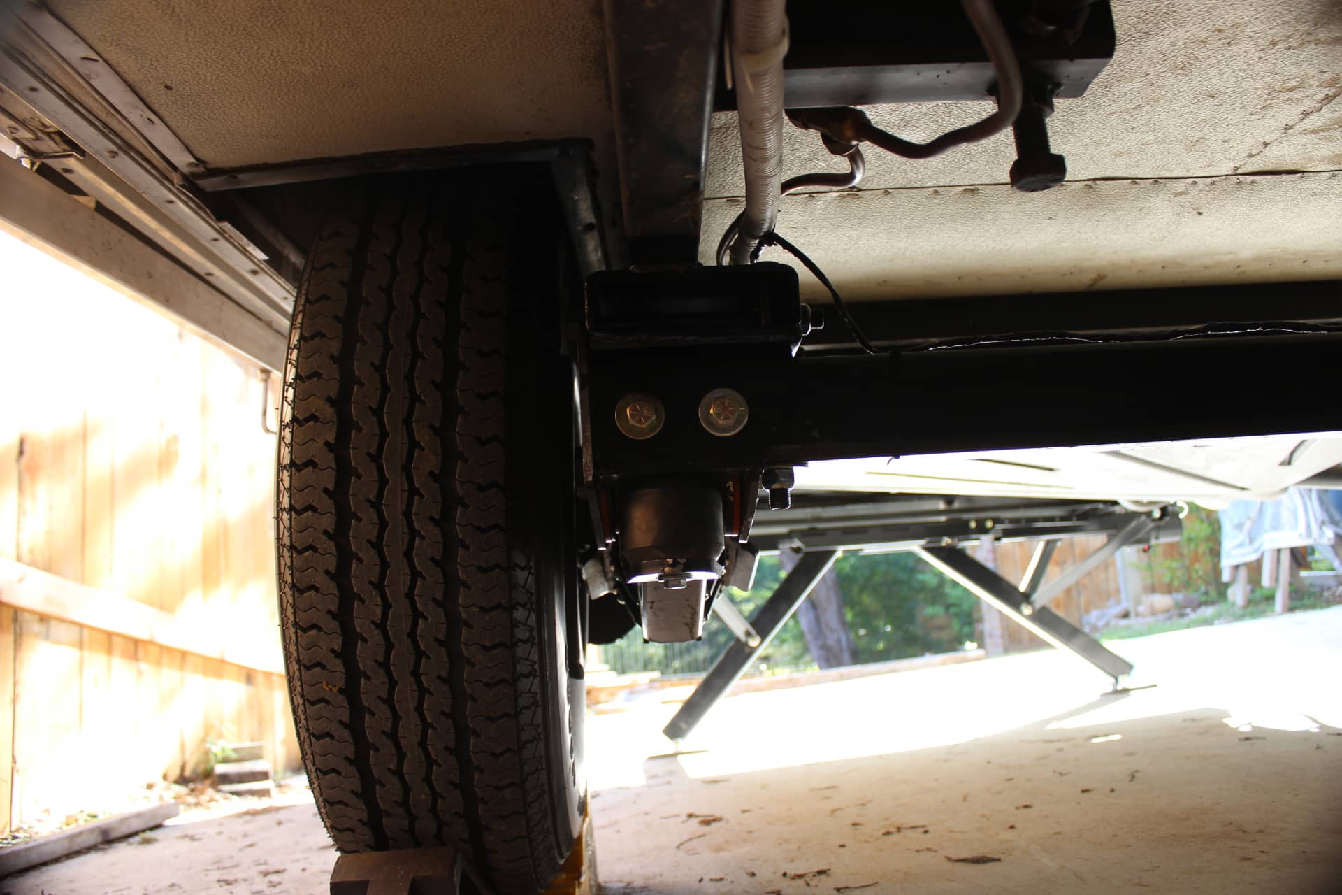
After dropping the old Dexter (images 1707, 1708, 0245, 0248, 0249, 0255) by taking off the four 15/16” bolts (images 0252, 0253) with an impact wrench, they measured the width between the insides of the frame (image 0251) to get the right length for the cross beam. Then they bolted the spindles to the suspensions with the extra long bolts (images 1691, 1697) and then the suspensions to the riser plates (images 0260, 0261, 0263, 0264) and raised it up into place with a floor jack (image 0268) to get it positioned correctly before welding the risers to the frame (images 0270, 1710).
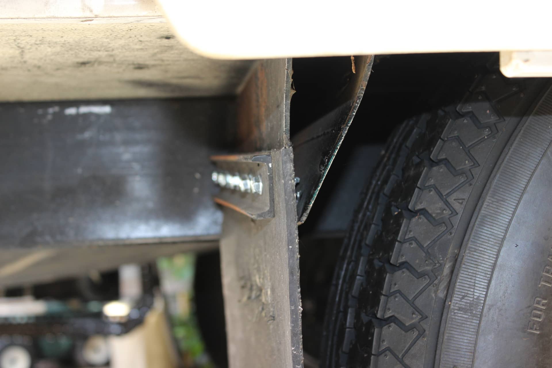
The outrigger from the frame on the right/passenger side behind the tire was a bit close clearance wise so they cut out the bottom of the outrigger and hammered (bent) the front vertical piece to the back vertical piece creating a slant or triangle behind the tire to give better clearance and welded the two together (images 1824, 1825, 1828). There’s plenty of clearance now.
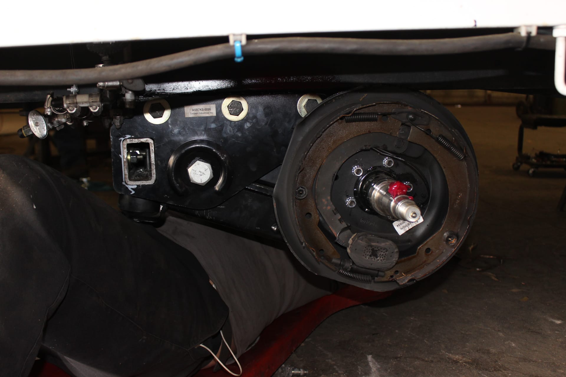
To tie it all up, they greased and installed the bearings, put the brake plates and hubs on the spindles and adjusted the brakes and finally the wheels were bolted on (images 1719, 1720).
Bulletproof.
That’s how I describe my TM now. It rolls like a dream with its heavy duty bearings and larger tires that will last longer because, even though I travel the same distance, they just don’t get around as much as my old 15”ers did! Go figure!